“Phasellus finibus enim nulla, quis ornare odio facilisis eu. Suspendisse ornare ante sit amet arcu semper, vel eleifend tortor egestas. Aenean luctus, lorem in hendrerit interdum.”

nisi tellus eleifend
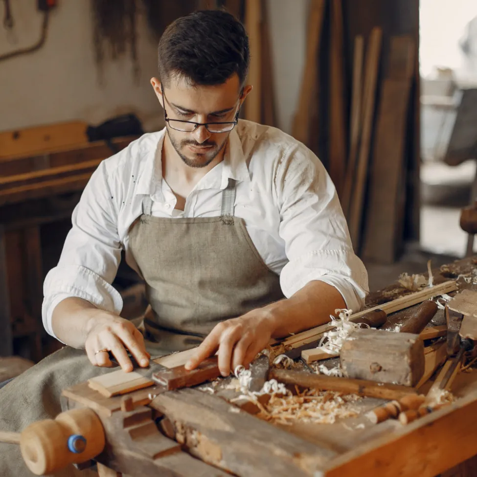
Furniture Production
Phasellus finibus enim
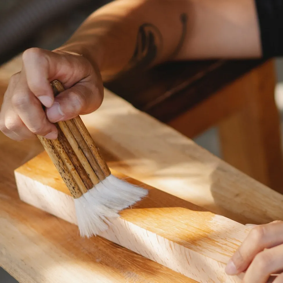
Furnitue
Repair
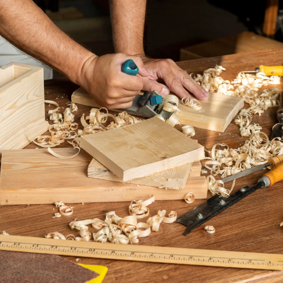
Carving Out Excellence
Integer ac interdum lacus. Nunc porta semper lacus a varius. Pellentesque habitant morbi tristique senectus et netus
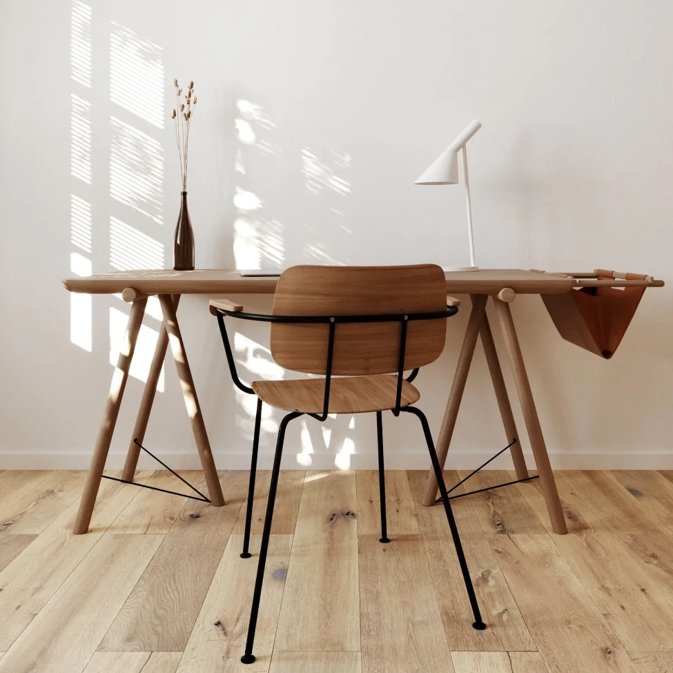
Our Services
Morbi mauris lacus consequat eget justo in semper gravida enim donec ultrices varius ligula.